A disassembly of the 64-byte version of Klappquadrat
====================================================
Klappquadrat (`klapquad.com`) is a 31-byte MS-DOS display hack (a
category known as the "32b intro") written by an entity known as T$.
Packaged in `klapquad.zip` is also a 64-byte version `quad_64b.com`
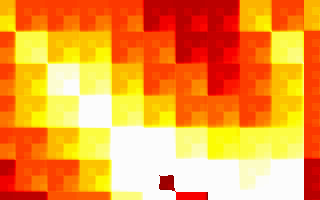
that makes even nicer graphics. Here's more or less how it looks in
DOSBox:
(video formats: 250kilobyte Ogg Theora or 4 megabyte ZMBV avi)
Very Basics: The Source
-----------------------
T$ was kind enough to include the assembly source to the 31-byte
version:
;Klappquadrat 32b
;32 byte intro source by T$
;Greets to mados, cthulhu, spacey and neo
org 100h
mov al,13h
int 10h
lds ax,[bx]
schleife:
mov ax,di
xor dx,dx
mov bx,320
div bx
;dx=x, ax=y
add ax,cx
add dx,cx
and ax,dx
shr ax,cl
xor [di],al
inc di
jnz schleife
inc cx
jmp short schleife
The 64-byte version looks fairly similar:
kragen@thrifty:~/pkgs/klapquad$ objdump -D -b binary -m i8086 -M intel quad_64b.com
quad_64b.com: file format binary
Disassembly of section .data:
0000000000000000 <.data>:
0: b0 13 mov al,0x13
2: cd 10 int 0x10
4: c5 07 lds ax,DWORD PTR [bx]
6: ba c9 03 mov dx,0x3c9
9: b5 03 mov ch,0x3
b: 66 c1 c8 08 ror eax,0x8
f: 3c 3f cmp al,0x3f
11: 72 04 jb 0x17
13: b0 3f mov al,0x3f
15: fe c4 inc ah
17: f6 c1 03 test cl,0x3
1a: 74 01 je 0x1d
1c: ee out [dx],al
1d: e2 ec loop 0xb
1f: 89 f8 mov ax,di
21: 31 d2 xor dx,dx
23: bb 40 01 mov bx,0x140
26: f7 f3 div bx
28: 01 c8 add ax,cx
2a: 01 ca add dx,cx
2c: 21 d0 and ax,dx
2e: c1 e8 03 shr ax,0x3
31: d3 e8 shr ax,cl
33: 00 05 add BYTE PTR [di],al
35: 47 inc di
36: 75 e7 jne 0x1f
38: 41 inc cx
39: e4 60 in al,0x60
3b: fe c8 dec al
3d: 75 e0 jne 0x1f
3f: c3 ret
The rest of this file is about 3000 words of my commentary on these 31
instructions. I might be wrong about some things, because I'm pretty
ignorant about assembly language and MS-DOS, and this code is a bit
clever. I'm mostly doing this to learn some of the tricks in the
code.
The Setup
---------
0: b0 13 mov al,0x13
2: cd 10 int 0x10
4: c5 07 lds ax,DWORD PTR [bx]
This part is in the original source; it's a pretty standard way to
start out a small graphics intro, like something in the 32b or 64b
categories. [fr-016][] starts the same way, but with a `les`
instead of a `lds`. `ax` starts out as 0, and in `int 10h`, `ah`
selects the service. Service 0 is setting the video mode; you specify
the video mode in `al`. So the first two instructions set the video
mode to mode 13h, which is the very handy 320x200x256 "MCGA" mode
supported by almost all SuperVGA cards.
[fr-016]: fr-016.html "My analysis of Farbrausch's fr-016: bytes"
See [my notes on fr-016][fr-016] for how the `lds` thing works,
although `fr-016` uses `les` instead of `lds`. Setting the `ds`
register like this makes the program code more or less inaccessible
for data operations.
The Palette Setup Loop
----------------------
6: ba c9 03 mov dx,0x3c9
9: b5 03 mov ch,0x3
Note that there's a `loop` instruction below that jumps to `0xb`, so
the above two instructions are setup for a loop. Here's the body of
the loop:
b: 66 c1 c8 08 ror eax,0x8
f: 3c 3f cmp al,0x3f
11: 72 04 jb 0x17
13: b0 3f mov al,0x3f
15: fe c4 inc ah
17: f6 c1 03 test cl,0x3
1a: 74 01 je 0x1d
1c: ee out [dx],al
1d: e2 ec loop 0xb
Loops generally need to have some kind of side effect in them to be
useful, and in this case, it looks like the purpose of the loop is the
`out` instruction, which writes the byte `al` to the port in `dx`;
`dx` got set in the loop setup code above to 3c9h, and isn't modified
inside the loop, so it's always writing bytes to this same port.
It turns out that this is the port you write bytes to in order to set
up the VGA palette, so this loop is there to set up the palette. This
25-byte loop (including the two-instruction setup) is also the major
difference between the 64-byte version and the 31-byte version whose
source is above.
The normal sequence, according to
, is that you write the
palette index to port 3c8h, then the six-bit red, green, and blue
values in sequence to port 3c9h. It says you can load the whole
palette by first writing a zero to 3c8h, and then writing all 256
palette entries in sequence to 3c9h. So I hypothesize that in general
you can write any number of palette entries in sequence this way, and
the (emulated) card happens to default to setting palette entry zero
at bootup.
Interestingly, this part of the program seems to work differently in
FreeDOS under QEMU than in DOSBox; the palette I get in FreeDOS is the
black, red, orange, yellow, white palette you can see in the
screenshot above, while the one I see in QEMU ranges from green
through yellow to white, with no black. I get a somewhat similar
effect, actually, if I run this program twice inside DOSBox, but it's
cyan instead of green.
This suggests that the problem is the initial state of the `eax`
register, and indeed if I insert an `xor eax, eax` at the beginning
of the program, it displays more correctly in FreeDOS in QEMU, and can
run more than once without screwing up the colors in DOSBox.
So, anyway, how does this loop produce this sequence of colors?
Presumably `ax` starts out as whatever the BIOS video mode routine
leaves in it. Each time through the loop, we rotate it by 8 bits, so
every four times through the loop, it will be rotated back to its
original position. The two bottom bits of the loop counter are tested
by the `test` instruction, and one time out of four, we skip the `out`
instruction, so one of the four bytes in `eax` is invisible.
This loop seems to set all 256 palette entries. At first that was
what I expected it to do, since that would be 3 * 256 color
components, and we set `cx` to 3 * 256 by setting `ch` to 3. But then
I thought that actually `cx` gets decremented by the `loop`
instruction even when we didn't output a color component, so I thought
it would only set the first 192 colors. But if I increase `ch` to 4,
then the first many colors all get set to white, I guess because it
wrapped around.
So, anyway, what were those colors? Here's the code that computes them.
b: 66 c1 c8 08 ror eax,0x8
f: 3c 3f cmp al,0x3f
11: 72 04 jb 0x17
13: b0 3f mov al,0x3f
15: fe c4 inc ah
So first it rotates `eax` by a byte; then it checks to see if the low
byte is greater than or equal to 0x3f, which is 63, the largest
six-bit value. If so, it thresholds it to 0x3f and increments `ah`,
the next byte up. So when red reaches its max, green starts to
increment, when green reaches its max, blue starts to increment; when
blue reaches its max, the invisible byte starts to increment; and when
the invisible byte reaches its max, red starts to increment. So, if
we start with some large number in the invisible byte, some small
number in the red byte, and zeroes elsewhere, this will give us the
dark red, light red, orange, yellow, white sequence that we see.
I seem to remember that this is what's called the "Dutch palette",
because so many demos from the Netherlands used it for a while.
I was surprised to learn that you could use `eax` in 16-bit real mode
like this. Apparently the operand size prefix 0x66 works in 16-bit
mode to give you 32-bit operands just as it works in 32-bit mode to
give you 16-bit operands.
So the remaining mysteries to me at this point were:
1. Why do all 256 palette entries get set, and not just 192 of them?
2. Where does the large number in the invisible byte (I guessed it's
`ah` on entry to the loop, but I was wrong) come from? It must be
something the BIOS `int 10h` call is sticking there, I incorrectly
thought, but what is it and what does it mean?
To answer these questions, I resorted to probing QEMU with GDB.
First, in QEMU's console, while running `quad_64b.com`:
(qemu) info registers
EAX=3f3f0000 EBX=...
...
ES =22e4 ...
CS =22e4 ...
So I can set a breakpoint at 0x22f40 and get it to stop on program
entry. GDB is kind of dumb when controlling QEMU in real mode; it can
set breakpoints, and it does stop when its breakpoints get hit, but it
can't figure out that it stopped because the breakpoint was hit, so
you have to manually remove the breakpoint if you want to continue,
and `stepi` doesn't work. Anyway, so I restarted QEMU and, before
restarting `quad_64b`, I said:
(qemu) gdbserver
(qemu)
And then I ran GDB:
kragen@thrifty:~/devel/circles$ gdb
GNU gdb 6.4.90-debian
...
(gdb) target remote localhost:1234
Remote debugging using localhost:1234
0x0000e830 in ?? ()
(gdb) set architecture i8086
The target architecture is assumed to be i8086
(gdb) b *0x22f40
Breakpoint 1 at 0x22f40
(gdb) c
Continuing.
And then I started the program:
A:\> quad_64b
And GDB woke up:
Program received signal SIGTRAP, Trace/breakpoint trap.
0x00000100 in ?? ()
(gdb) x/40i $cs*16+$eip
0x22f40: mov $0x13,%al
0x22f42: int $0x10
0x22f44: lds (%bx),%ax
0x22f46: mov $0x3c9,%dx
0x22f49: mov $0x3,%ch
0x22f4b: ror $0x8,%eax
...
So I set breakpoints after the return from the interrupt, and at the
top of the loop body, and deleted the breakpoint where I was:
(gdb) b *0x22f44
Breakpoint 2 at 0x22f44
(gdb) b *0x22f4b
Breakpoint 3 at 0x22f4b
(gdb) delete 1
(gdb) c
Continuing.
Program received signal SIGTRAP, Trace/breakpoint trap.
0x00000104 in ?? ()
(gdb) info registers
eax 0x400020 4194336
ecx 0xff 255
...
So there are two interesting things. First, there is a byte that's
more than 0x3f in `eax`, and it's the green byte, which explains the
green color I get when testing in QEMU with FreeDOS. Third, `ecx` is
0xff, not 0; this explains why all of the palette entries get set,
instead of only three-quarters of them. (Also, it means the invisible
byte, the one to be skipped, will be the one in `al` at the end of the
fourth, eighth, etc., iterations of the loop, not the first, fifth,
etc. This is taken into account in my naming of the bytes above.)
Unfortunately, around this point I screwed up in GDB and had to start
QEMU again and reattach GDB, and then redelete some old breakpoints.
(gdb) c
Continuing.
Watchdog has expired. Target detached.
(gdb) target remote localhost:1234
Remote debugging using localhost:1234
0x0000026f in ?? ()
(gdb) display/2i $cs*16+$eip
2: x/2i $cs * 16 + $eip
0x96f: mov 1(%bx),%al
0x972: mov 13(%bx),%ah
(gdb) b *0x22f40
Note: breakpoint 5 also set at pc 0x22f40.
Breakpoint 6 at 0x22f40
(gdb) delete 5
(gdb) c
Continuing.
Program received signal SIGTRAP, Trace/breakpoint trap.
0x00000100 in ?? ()
2: x/2i $cs * 16 + $eip
0x22f40: mov $0x13,%al
0x22f42: int $0x10
(gdb) info registers
eax 0x400000 4194304
ecx 0xff 255
...
(gdb) p $eax = 0x0
$6 = 0
(gdb) b *0x22f46
Breakpoint 7 at 0x22f46
(gdb) delete 6
(gdb) c
Continuing.
Program received signal SIGTRAP, Trace/breakpoint trap.
0x00000106 in ?? ()
2: x/2i $cs * 16 + $eip
0x22f46: mov $0x3c9,%dx
0x22f49: mov $0x3,%ch
(gdb) info registers
eax 0x20cd 8397
ecx 0xff 255
...
(gdb)
So `ecx` is 255 upon program entry, and it's not the BIOS that's
setting %eax after all; it's the `lds` instruction, which loads the
`int 20h` instruction from the beginning of the PSP into it! So red
starts out at 0x20, and the invisible byte starts out at 0xcd, the
`int` opcode, which is above 0x3f, so that's how the incrementation
gets started.
The Main Loop
-------------
Here's the main loop, minus the exit test at the end, which just jumps
back to the beginning:
1f: 89 f8 mov ax,di
21: 31 d2 xor dx,dx
23: bb 40 01 mov bx,0x140
26: f7 f3 div bx
28: 01 c8 add ax,cx
2a: 01 ca add dx,cx
2c: 21 d0 and ax,dx
2e: c1 e8 03 shr ax,0x3
31: d3 e8 shr ax,cl
33: 00 05 add BYTE PTR [di],al
35: 47 inc di
36: 75 e7 jne 0x1f
38: 41 inc cx
So the main thing to notice here is that there's only one memory
access here, and it's through the `di` register; and `di` changes only
by being incremented. So we're writing to each pixel on the screen
sequentially (remember, `ds` is set to the video segment a000h early
on.).
This loop is almost the same as the one in the 31-byte version. There
are two differences:
- the operation on each pixel is an `add` rather than an `xor`;
- there's an additional `shr` by a constant 3.
Let's take a look at the last bit first:
35: 47 inc di
36: 75 e7 jne 0x1f
38: 41 inc cx
On entry to this loop, `cx` is zero; we know this because we just fell
out of the bottom of a `loop` instruction, which decrements `cx` and
jumps unless it decremented it to zero. But every time `di` hits zero
(that is, wraps around to the top of the screen) we increment `cx`
again. There are no other places in the loop that change `cx`. So it
forms a kind of frame counter.
The first little bit:
1f: 89 f8 mov ax,di
21: 31 d2 xor dx,dx
23: bb 40 01 mov bx,0x140
26: f7 f3 div bx
has a helpful comment in the source:
;dx=x, ax=y
0x140 is 320, the number of pixels in a row on the mode 13h screen,
and since there's one byte per pixel, also the number of bytes. So if
`di` points at a pixel, dividing `di` by 320 should give us the
Y-coordinate as the quotient and the X-coordinate as the remainder;
and that's what the comment means.
The next few instructions are where the black magic happens:
28: 01 c8 add ax,cx
2a: 01 ca add dx,cx
2c: 21 d0 and ax,dx
2e: c1 e8 03 shr ax,0x3
31: d3 e8 shr ax,cl
33: 00 05 add BYTE PTR [di],al
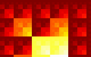
The first two `add` instructions essentially shift the coordinates
up and to the left by one pixel every frame. If you take them out,
you get a much flatter-looking picture, one that looks like this:
The three-bit `shr` is also kind of optional. It throws away the
bottom three bits of coordinate-derived data, which means that the
screen is divided into a bunch of 8x8 tiles, and there are no
differences introduced inside those tiles (although the per-frame
shift can introduce some). Without the `add`s and this extra `shr`,
you get something that looks mostly like a bunch of particularly
colorful Sierpinski triangles.
The extra `shr` also slows things down a bit; without it, in some
pixels (e.g. (255, 255)), you can get all the way to palette value 255
in a single frame!
So these lines are kind of the heart of the hack:
2c: 21 d0 and ax,dx
31: d3 e8 shr ax,cl
33: 00 05 add BYTE PTR [di],al
With them in there, you get most of the visual and temporal features
of the original.
You'll notice that the screenshots all appear to be made up of nested
2x2 squares in which the bottom right quadrant of each square is
brighter than the other three quadrants. That's kind of what you'd
expect if you `and` your coordinates together, right? The lower right
quadrant of each 2x2 square is the one where both of the coordinate
bits distinguishing the quadrants of that square are 1.
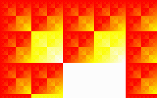
That's pretty much the pattern you get if you just do this:
2c: 21 d0 and ax,dx
33: 00 05 mov BYTE PTR [di],al
Which looks like this, and doesn't animate:
I don't know how to completely explain the difference between that and
the previous picture. Obviously the frame counter is crucial in
actually getting an animation, and during the long period of time when
`cl` is counting up from 8 to 256, the animation essentially pauses;
but I don't quite know how to explain the difference it makes.
That's the main part of my understanding of Klappquadrat I'm still not
yet happy with.
The Exit Test
-------------
39: e4 60 in al,0x60
3b: fe c8 dec al
3d: 75 e0 jne 0x1f
3f: c3 ret
According to the source for Dirojed, another 32-byte intro, these four
instructions are the "standard ESC check". I guess port 60h reads as
1 if somebody's hitting the Esc key and something else otherwise; so
decrementing `al` sets the zero flag iff Esc was pressed, and if that
was the case, we fall through to the `ret`, which pops a zero off the
stack, returns to the `int 20h` at the beginning of the PSP, and
terminates the program. About half the time, this crashes FreeDOS in
QEMU; I don't know why.
The 31-byte version just has an unconditional `jmp short schliefe`
here instead of this ESC check, so there's no way to exit to DOS.
My `gas` Version
----------------
I hand-translated the `objdump` disassembly output into equivalent
`gas` input to facilitate experimenting with changes to the program.
It produces a byte-for-byte identical executable until you uncomment
some of the lines that make it a little more robust. It looks like
this:
## a copy of T$'s 64-byte "Klappquadrat"
## compile as follows:
## as -R klapquad.s -o klapquad.o
## objcopy -O binary klapquad.o klapquad.com.0
## dd if=klapquad.com.0 of=klapquad.com bs=256 skip=1
.code16
.org 0x100
## this makes it work right in FreeDOS in QEMU
## and when run multiple times
#xor %eax, %eax
movb $0x13, %al
int $0x10
#mov $(vidseg-2), %bx # makes it work right in FreeDOS in QEMU
lds (%bx), %ax
mov $0x3c9, %dx
mov $3, %ch # orig. 3
set_palette_loop:
ror $8, %eax
cmp $0x3f, %al
jb dont_threshold
mov $0x3f, %al
inc %ah
dont_threshold:
test $3, %cl
je dont_outb
outb %al, (%dx)
dont_outb:
loop set_palette_loop
schleife:
mov %di, %ax
xor %dx, %dx
mov $0x140, %bx
div %bx
add %cx, %ax
add %cx, %dx
and %dx, %ax
shr $3, %ax
shr %cl, %ax
addb %al, (%di)
inc %di
jne schleife
inc %cx
in $0x60, %al
dec %al
jne schleife
ret
#vidseg: .short 0xa000
My Python version
-----------------
There seem to be a limited number of people who can appreciate the
assembly version, even with the explanation, and it is a little hard
to modify; so I wrote this Python version, which I am placing in the
public domain. It probably isn't easier to run (you need to install
Python, Numeric, SDL, and Pygame instead of any one of DOSBox,
Microsoft Windows, or FreeDOS, and QEMU, and the MS-DOS interfaces are
probably stabler) but it's sure easier to read if you know Python and
not assembly.
#!/usr/bin/python
"""Recreation of T$'s Klappquadrat intro in Python with Pygame and Numeric.
This is a recreation of the 64-byte version, and I think 31
instructions. By contrast, this is 44 lines of code, about 1600
characters. On the other hand, you can change this from 320x200x256
to, say, 640x480x512 by changing the screensize= and ncolors= lines to
say (640, 480) and 512.
Kragen Javier Sitaker wrote this recreation, but T$ is to credit for
the original intro.
"""
import pygame, sys
from Numeric import zeros, subtract, array, arange, where, take, shape, indices
screensize = (320, 200)
ncolors = 256
def colors(masks, levels):
"Compute a grayscale pixel from bit masks and a floating-point level [0,1)"
return sum([int(mask * level) & mask for mask, level in zip(masks, levels)])
def clamp(a, b, c):
"Threshold b between lower limit a and upper limit c."
d = where(a < b, b, a)
return where(d < c, d, c)
def redraw(screen, buf, palette, frames):
x, y = indices(screensize)
# this 256 is not ncolors; it's a timing/pacing thing
buf += ((x + frames) & (y + frames)) >> (frames % 256) >> 3
buf %= ncolors
pygame.surfarray.blit_array(screen, take(palette, buf))
def main(argv):
pygame.init()
screen = pygame.display.set_mode(screensize, pygame.FULLSCREEN)
buf = zeros(screensize)
fiery_rgb_integers = clamp(0, subtract.outer(arange(ncolors) + ncolors/8,
((array([0, 1, 2]) * ncolors)
/ 4)),
ncolors / 4)
masks = screen.get_masks()[:3]
# I'm not sure this palette is exactly right; it only goes to 63
# in the original...
palette = array([colors(masks, levels/float(ncolors/4))
for levels in fiery_rgb_integers])
frames = 0
while 1:
ev = pygame.event.poll()
if ev.type == pygame.NOEVENT:
frames += 1
redraw(screen, buf, palette, frames)
pygame.display.flip()
elif ev.type == pygame.KEYDOWN: break
elif ev.type == pygame.QUIT: break
if __name__ == '__main__': main(sys.argv)
 (video formats: 250kilobyte Ogg Theora or 4 megabyte ZMBV avi)
Very Basics: The Source
-----------------------
T$ was kind enough to include the assembly source to the 31-byte
version:
;Klappquadrat 32b
;32 byte intro source by T$
;Greets to mados, cthulhu, spacey and neo
org 100h
mov al,13h
int 10h
lds ax,[bx]
schleife:
mov ax,di
xor dx,dx
mov bx,320
div bx
;dx=x, ax=y
add ax,cx
add dx,cx
and ax,dx
shr ax,cl
xor [di],al
inc di
jnz schleife
inc cx
jmp short schleife
The 64-byte version looks fairly similar:
kragen@thrifty:~/pkgs/klapquad$ objdump -D -b binary -m i8086 -M intel quad_64b.com
quad_64b.com: file format binary
Disassembly of section .data:
0000000000000000 <.data>:
0: b0 13 mov al,0x13
2: cd 10 int 0x10
4: c5 07 lds ax,DWORD PTR [bx]
6: ba c9 03 mov dx,0x3c9
9: b5 03 mov ch,0x3
b: 66 c1 c8 08 ror eax,0x8
f: 3c 3f cmp al,0x3f
11: 72 04 jb 0x17
13: b0 3f mov al,0x3f
15: fe c4 inc ah
17: f6 c1 03 test cl,0x3
1a: 74 01 je 0x1d
1c: ee out [dx],al
1d: e2 ec loop 0xb
1f: 89 f8 mov ax,di
21: 31 d2 xor dx,dx
23: bb 40 01 mov bx,0x140
26: f7 f3 div bx
28: 01 c8 add ax,cx
2a: 01 ca add dx,cx
2c: 21 d0 and ax,dx
2e: c1 e8 03 shr ax,0x3
31: d3 e8 shr ax,cl
33: 00 05 add BYTE PTR [di],al
35: 47 inc di
36: 75 e7 jne 0x1f
38: 41 inc cx
39: e4 60 in al,0x60
3b: fe c8 dec al
3d: 75 e0 jne 0x1f
3f: c3 ret
The rest of this file is about 3000 words of my commentary on these 31
instructions. I might be wrong about some things, because I'm pretty
ignorant about assembly language and MS-DOS, and this code is a bit
clever. I'm mostly doing this to learn some of the tricks in the
code.
The Setup
---------
0: b0 13 mov al,0x13
2: cd 10 int 0x10
4: c5 07 lds ax,DWORD PTR [bx]
This part is in the original source; it's a pretty standard way to
start out a small graphics intro, like something in the 32b or 64b
categories. [fr-016][] starts the same way, but with a `les`
instead of a `lds`. `ax` starts out as 0, and in `int 10h`, `ah`
selects the service. Service 0 is setting the video mode; you specify
the video mode in `al`. So the first two instructions set the video
mode to mode 13h, which is the very handy 320x200x256 "MCGA" mode
supported by almost all SuperVGA cards.
[fr-016]: fr-016.html "My analysis of Farbrausch's fr-016: bytes"
See [my notes on fr-016][fr-016] for how the `lds` thing works,
although `fr-016` uses `les` instead of `lds`. Setting the `ds`
register like this makes the program code more or less inaccessible
for data operations.
The Palette Setup Loop
----------------------
6: ba c9 03 mov dx,0x3c9
9: b5 03 mov ch,0x3
Note that there's a `loop` instruction below that jumps to `0xb`, so
the above two instructions are setup for a loop. Here's the body of
the loop:
b: 66 c1 c8 08 ror eax,0x8
f: 3c 3f cmp al,0x3f
11: 72 04 jb 0x17
13: b0 3f mov al,0x3f
15: fe c4 inc ah
17: f6 c1 03 test cl,0x3
1a: 74 01 je 0x1d
1c: ee out [dx],al
1d: e2 ec loop 0xb
Loops generally need to have some kind of side effect in them to be
useful, and in this case, it looks like the purpose of the loop is the
`out` instruction, which writes the byte `al` to the port in `dx`;
`dx` got set in the loop setup code above to 3c9h, and isn't modified
inside the loop, so it's always writing bytes to this same port.
It turns out that this is the port you write bytes to in order to set
up the VGA palette, so this loop is there to set up the palette. This
25-byte loop (including the two-instruction setup) is also the major
difference between the 64-byte version and the 31-byte version whose
source is above.
The normal sequence, according to
(video formats: 250kilobyte Ogg Theora or 4 megabyte ZMBV avi)
Very Basics: The Source
-----------------------
T$ was kind enough to include the assembly source to the 31-byte
version:
;Klappquadrat 32b
;32 byte intro source by T$
;Greets to mados, cthulhu, spacey and neo
org 100h
mov al,13h
int 10h
lds ax,[bx]
schleife:
mov ax,di
xor dx,dx
mov bx,320
div bx
;dx=x, ax=y
add ax,cx
add dx,cx
and ax,dx
shr ax,cl
xor [di],al
inc di
jnz schleife
inc cx
jmp short schleife
The 64-byte version looks fairly similar:
kragen@thrifty:~/pkgs/klapquad$ objdump -D -b binary -m i8086 -M intel quad_64b.com
quad_64b.com: file format binary
Disassembly of section .data:
0000000000000000 <.data>:
0: b0 13 mov al,0x13
2: cd 10 int 0x10
4: c5 07 lds ax,DWORD PTR [bx]
6: ba c9 03 mov dx,0x3c9
9: b5 03 mov ch,0x3
b: 66 c1 c8 08 ror eax,0x8
f: 3c 3f cmp al,0x3f
11: 72 04 jb 0x17
13: b0 3f mov al,0x3f
15: fe c4 inc ah
17: f6 c1 03 test cl,0x3
1a: 74 01 je 0x1d
1c: ee out [dx],al
1d: e2 ec loop 0xb
1f: 89 f8 mov ax,di
21: 31 d2 xor dx,dx
23: bb 40 01 mov bx,0x140
26: f7 f3 div bx
28: 01 c8 add ax,cx
2a: 01 ca add dx,cx
2c: 21 d0 and ax,dx
2e: c1 e8 03 shr ax,0x3
31: d3 e8 shr ax,cl
33: 00 05 add BYTE PTR [di],al
35: 47 inc di
36: 75 e7 jne 0x1f
38: 41 inc cx
39: e4 60 in al,0x60
3b: fe c8 dec al
3d: 75 e0 jne 0x1f
3f: c3 ret
The rest of this file is about 3000 words of my commentary on these 31
instructions. I might be wrong about some things, because I'm pretty
ignorant about assembly language and MS-DOS, and this code is a bit
clever. I'm mostly doing this to learn some of the tricks in the
code.
The Setup
---------
0: b0 13 mov al,0x13
2: cd 10 int 0x10
4: c5 07 lds ax,DWORD PTR [bx]
This part is in the original source; it's a pretty standard way to
start out a small graphics intro, like something in the 32b or 64b
categories. [fr-016][] starts the same way, but with a `les`
instead of a `lds`. `ax` starts out as 0, and in `int 10h`, `ah`
selects the service. Service 0 is setting the video mode; you specify
the video mode in `al`. So the first two instructions set the video
mode to mode 13h, which is the very handy 320x200x256 "MCGA" mode
supported by almost all SuperVGA cards.
[fr-016]: fr-016.html "My analysis of Farbrausch's fr-016: bytes"
See [my notes on fr-016][fr-016] for how the `lds` thing works,
although `fr-016` uses `les` instead of `lds`. Setting the `ds`
register like this makes the program code more or less inaccessible
for data operations.
The Palette Setup Loop
----------------------
6: ba c9 03 mov dx,0x3c9
9: b5 03 mov ch,0x3
Note that there's a `loop` instruction below that jumps to `0xb`, so
the above two instructions are setup for a loop. Here's the body of
the loop:
b: 66 c1 c8 08 ror eax,0x8
f: 3c 3f cmp al,0x3f
11: 72 04 jb 0x17
13: b0 3f mov al,0x3f
15: fe c4 inc ah
17: f6 c1 03 test cl,0x3
1a: 74 01 je 0x1d
1c: ee out [dx],al
1d: e2 ec loop 0xb
Loops generally need to have some kind of side effect in them to be
useful, and in this case, it looks like the purpose of the loop is the
`out` instruction, which writes the byte `al` to the port in `dx`;
`dx` got set in the loop setup code above to 3c9h, and isn't modified
inside the loop, so it's always writing bytes to this same port.
It turns out that this is the port you write bytes to in order to set
up the VGA palette, so this loop is there to set up the palette. This
25-byte loop (including the two-instruction setup) is also the major
difference between the 64-byte version and the 31-byte version whose
source is above.
The normal sequence, according to
 The three-bit `shr` is also kind of optional. It throws away the
bottom three bits of coordinate-derived data, which means that the
screen is divided into a bunch of 8x8 tiles, and there are no
differences introduced inside those tiles (although the per-frame
shift can introduce some). Without the `add`s and this extra `shr`,
you get something that looks mostly like a bunch of particularly
colorful Sierpinski triangles.
The extra `shr` also slows things down a bit; without it, in some
pixels (e.g. (255, 255)), you can get all the way to palette value 255
in a single frame!
So these lines are kind of the heart of the hack:
2c: 21 d0 and ax,dx
31: d3 e8 shr ax,cl
33: 00 05 add BYTE PTR [di],al
With them in there, you get most of the visual and temporal features
of the original.
You'll notice that the screenshots all appear to be made up of nested
2x2 squares in which the bottom right quadrant of each square is
brighter than the other three quadrants. That's kind of what you'd
expect if you `and` your coordinates together, right? The lower right
quadrant of each 2x2 square is the one where both of the coordinate
bits distinguishing the quadrants of that square are 1.
That's pretty much the pattern you get if you just do this:
2c: 21 d0 and ax,dx
33: 00 05 mov BYTE PTR [di],al
Which looks like this, and doesn't animate:
The three-bit `shr` is also kind of optional. It throws away the
bottom three bits of coordinate-derived data, which means that the
screen is divided into a bunch of 8x8 tiles, and there are no
differences introduced inside those tiles (although the per-frame
shift can introduce some). Without the `add`s and this extra `shr`,
you get something that looks mostly like a bunch of particularly
colorful Sierpinski triangles.
The extra `shr` also slows things down a bit; without it, in some
pixels (e.g. (255, 255)), you can get all the way to palette value 255
in a single frame!
So these lines are kind of the heart of the hack:
2c: 21 d0 and ax,dx
31: d3 e8 shr ax,cl
33: 00 05 add BYTE PTR [di],al
With them in there, you get most of the visual and temporal features
of the original.
You'll notice that the screenshots all appear to be made up of nested
2x2 squares in which the bottom right quadrant of each square is
brighter than the other three quadrants. That's kind of what you'd
expect if you `and` your coordinates together, right? The lower right
quadrant of each 2x2 square is the one where both of the coordinate
bits distinguishing the quadrants of that square are 1.
That's pretty much the pattern you get if you just do this:
2c: 21 d0 and ax,dx
33: 00 05 mov BYTE PTR [di],al
Which looks like this, and doesn't animate:
 I don't know how to completely explain the difference between that and
the previous picture. Obviously the frame counter is crucial in
actually getting an animation, and during the long period of time when
`cl` is counting up from 8 to 256, the animation essentially pauses;
but I don't quite know how to explain the difference it makes.
That's the main part of my understanding of Klappquadrat I'm still not
yet happy with.
The Exit Test
-------------
39: e4 60 in al,0x60
3b: fe c8 dec al
3d: 75 e0 jne 0x1f
3f: c3 ret
According to the source for Dirojed, another 32-byte intro, these four
instructions are the "standard ESC check". I guess port 60h reads as
1 if somebody's hitting the Esc key and something else otherwise; so
decrementing `al` sets the zero flag iff Esc was pressed, and if that
was the case, we fall through to the `ret`, which pops a zero off the
stack, returns to the `int 20h` at the beginning of the PSP, and
terminates the program. About half the time, this crashes FreeDOS in
QEMU; I don't know why.
The 31-byte version just has an unconditional `jmp short schliefe`
here instead of this ESC check, so there's no way to exit to DOS.
My `gas` Version
----------------
I hand-translated the `objdump` disassembly output into equivalent
`gas` input to facilitate experimenting with changes to the program.
It produces a byte-for-byte identical executable until you uncomment
some of the lines that make it a little more robust. It looks like
this:
## a copy of T$'s 64-byte "Klappquadrat"
## compile as follows:
## as -R klapquad.s -o klapquad.o
## objcopy -O binary klapquad.o klapquad.com.0
## dd if=klapquad.com.0 of=klapquad.com bs=256 skip=1
.code16
.org 0x100
## this makes it work right in FreeDOS in QEMU
## and when run multiple times
#xor %eax, %eax
movb $0x13, %al
int $0x10
#mov $(vidseg-2), %bx # makes it work right in FreeDOS in QEMU
lds (%bx), %ax
mov $0x3c9, %dx
mov $3, %ch # orig. 3
set_palette_loop:
ror $8, %eax
cmp $0x3f, %al
jb dont_threshold
mov $0x3f, %al
inc %ah
dont_threshold:
test $3, %cl
je dont_outb
outb %al, (%dx)
dont_outb:
loop set_palette_loop
schleife:
mov %di, %ax
xor %dx, %dx
mov $0x140, %bx
div %bx
add %cx, %ax
add %cx, %dx
and %dx, %ax
shr $3, %ax
shr %cl, %ax
addb %al, (%di)
inc %di
jne schleife
inc %cx
in $0x60, %al
dec %al
jne schleife
ret
#vidseg: .short 0xa000
My Python version
-----------------
There seem to be a limited number of people who can appreciate the
assembly version, even with the explanation, and it is a little hard
to modify; so I wrote this Python version, which I am placing in the
public domain. It probably isn't easier to run (you need to install
Python, Numeric, SDL, and Pygame instead of any one of DOSBox,
Microsoft Windows, or FreeDOS, and QEMU, and the MS-DOS interfaces are
probably stabler) but it's sure easier to read if you know Python and
not assembly.
#!/usr/bin/python
"""Recreation of T$'s Klappquadrat intro in Python with Pygame and Numeric.
This is a recreation of the 64-byte version, and I think 31
instructions. By contrast, this is 44 lines of code, about 1600
characters. On the other hand, you can change this from 320x200x256
to, say, 640x480x512 by changing the screensize= and ncolors= lines to
say (640, 480) and 512.
Kragen Javier Sitaker wrote this recreation, but T$ is to credit for
the original intro.
"""
import pygame, sys
from Numeric import zeros, subtract, array, arange, where, take, shape, indices
screensize = (320, 200)
ncolors = 256
def colors(masks, levels):
"Compute a grayscale pixel from bit masks and a floating-point level [0,1)"
return sum([int(mask * level) & mask for mask, level in zip(masks, levels)])
def clamp(a, b, c):
"Threshold b between lower limit a and upper limit c."
d = where(a < b, b, a)
return where(d < c, d, c)
def redraw(screen, buf, palette, frames):
x, y = indices(screensize)
# this 256 is not ncolors; it's a timing/pacing thing
buf += ((x + frames) & (y + frames)) >> (frames % 256) >> 3
buf %= ncolors
pygame.surfarray.blit_array(screen, take(palette, buf))
def main(argv):
pygame.init()
screen = pygame.display.set_mode(screensize, pygame.FULLSCREEN)
buf = zeros(screensize)
fiery_rgb_integers = clamp(0, subtract.outer(arange(ncolors) + ncolors/8,
((array([0, 1, 2]) * ncolors)
/ 4)),
ncolors / 4)
masks = screen.get_masks()[:3]
# I'm not sure this palette is exactly right; it only goes to 63
# in the original...
palette = array([colors(masks, levels/float(ncolors/4))
for levels in fiery_rgb_integers])
frames = 0
while 1:
ev = pygame.event.poll()
if ev.type == pygame.NOEVENT:
frames += 1
redraw(screen, buf, palette, frames)
pygame.display.flip()
elif ev.type == pygame.KEYDOWN: break
elif ev.type == pygame.QUIT: break
if __name__ == '__main__': main(sys.argv)
I don't know how to completely explain the difference between that and
the previous picture. Obviously the frame counter is crucial in
actually getting an animation, and during the long period of time when
`cl` is counting up from 8 to 256, the animation essentially pauses;
but I don't quite know how to explain the difference it makes.
That's the main part of my understanding of Klappquadrat I'm still not
yet happy with.
The Exit Test
-------------
39: e4 60 in al,0x60
3b: fe c8 dec al
3d: 75 e0 jne 0x1f
3f: c3 ret
According to the source for Dirojed, another 32-byte intro, these four
instructions are the "standard ESC check". I guess port 60h reads as
1 if somebody's hitting the Esc key and something else otherwise; so
decrementing `al` sets the zero flag iff Esc was pressed, and if that
was the case, we fall through to the `ret`, which pops a zero off the
stack, returns to the `int 20h` at the beginning of the PSP, and
terminates the program. About half the time, this crashes FreeDOS in
QEMU; I don't know why.
The 31-byte version just has an unconditional `jmp short schliefe`
here instead of this ESC check, so there's no way to exit to DOS.
My `gas` Version
----------------
I hand-translated the `objdump` disassembly output into equivalent
`gas` input to facilitate experimenting with changes to the program.
It produces a byte-for-byte identical executable until you uncomment
some of the lines that make it a little more robust. It looks like
this:
## a copy of T$'s 64-byte "Klappquadrat"
## compile as follows:
## as -R klapquad.s -o klapquad.o
## objcopy -O binary klapquad.o klapquad.com.0
## dd if=klapquad.com.0 of=klapquad.com bs=256 skip=1
.code16
.org 0x100
## this makes it work right in FreeDOS in QEMU
## and when run multiple times
#xor %eax, %eax
movb $0x13, %al
int $0x10
#mov $(vidseg-2), %bx # makes it work right in FreeDOS in QEMU
lds (%bx), %ax
mov $0x3c9, %dx
mov $3, %ch # orig. 3
set_palette_loop:
ror $8, %eax
cmp $0x3f, %al
jb dont_threshold
mov $0x3f, %al
inc %ah
dont_threshold:
test $3, %cl
je dont_outb
outb %al, (%dx)
dont_outb:
loop set_palette_loop
schleife:
mov %di, %ax
xor %dx, %dx
mov $0x140, %bx
div %bx
add %cx, %ax
add %cx, %dx
and %dx, %ax
shr $3, %ax
shr %cl, %ax
addb %al, (%di)
inc %di
jne schleife
inc %cx
in $0x60, %al
dec %al
jne schleife
ret
#vidseg: .short 0xa000
My Python version
-----------------
There seem to be a limited number of people who can appreciate the
assembly version, even with the explanation, and it is a little hard
to modify; so I wrote this Python version, which I am placing in the
public domain. It probably isn't easier to run (you need to install
Python, Numeric, SDL, and Pygame instead of any one of DOSBox,
Microsoft Windows, or FreeDOS, and QEMU, and the MS-DOS interfaces are
probably stabler) but it's sure easier to read if you know Python and
not assembly.
#!/usr/bin/python
"""Recreation of T$'s Klappquadrat intro in Python with Pygame and Numeric.
This is a recreation of the 64-byte version, and I think 31
instructions. By contrast, this is 44 lines of code, about 1600
characters. On the other hand, you can change this from 320x200x256
to, say, 640x480x512 by changing the screensize= and ncolors= lines to
say (640, 480) and 512.
Kragen Javier Sitaker wrote this recreation, but T$ is to credit for
the original intro.
"""
import pygame, sys
from Numeric import zeros, subtract, array, arange, where, take, shape, indices
screensize = (320, 200)
ncolors = 256
def colors(masks, levels):
"Compute a grayscale pixel from bit masks and a floating-point level [0,1)"
return sum([int(mask * level) & mask for mask, level in zip(masks, levels)])
def clamp(a, b, c):
"Threshold b between lower limit a and upper limit c."
d = where(a < b, b, a)
return where(d < c, d, c)
def redraw(screen, buf, palette, frames):
x, y = indices(screensize)
# this 256 is not ncolors; it's a timing/pacing thing
buf += ((x + frames) & (y + frames)) >> (frames % 256) >> 3
buf %= ncolors
pygame.surfarray.blit_array(screen, take(palette, buf))
def main(argv):
pygame.init()
screen = pygame.display.set_mode(screensize, pygame.FULLSCREEN)
buf = zeros(screensize)
fiery_rgb_integers = clamp(0, subtract.outer(arange(ncolors) + ncolors/8,
((array([0, 1, 2]) * ncolors)
/ 4)),
ncolors / 4)
masks = screen.get_masks()[:3]
# I'm not sure this palette is exactly right; it only goes to 63
# in the original...
palette = array([colors(masks, levels/float(ncolors/4))
for levels in fiery_rgb_integers])
frames = 0
while 1:
ev = pygame.event.poll()
if ev.type == pygame.NOEVENT:
frames += 1
redraw(screen, buf, palette, frames)
pygame.display.flip()
elif ev.type == pygame.KEYDOWN: break
elif ev.type == pygame.QUIT: break
if __name__ == '__main__': main(sys.argv)